 Figpea
Path Editing Tool
Overview
The Path Editing Tool provides a powerful way to create and modify vector paths in Figpea. With this tool, you can precisely control every aspect of your SVG paths, from simple lines to complex curves with multiple control points.
Getting Started
To edit a path:
- Select a path layer in your document
- Press Enter or click the "Edit Path" button in the properties panel (pressing Enter on a non-path shape converts it to a path first)
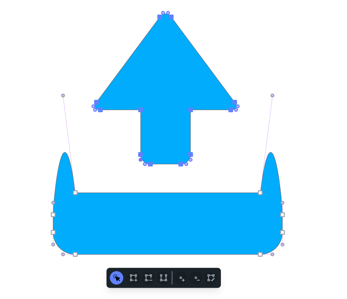


- The path editing interface will appear, showing all anchor points and control handles
- When you're done, leave path editing with Esc,
Ctrl/Cmd + Enter, or the Stop Editing button in the properties panel. Your edits are kept — leaving the mode never discards them.
Drawing a New Path with the Pen
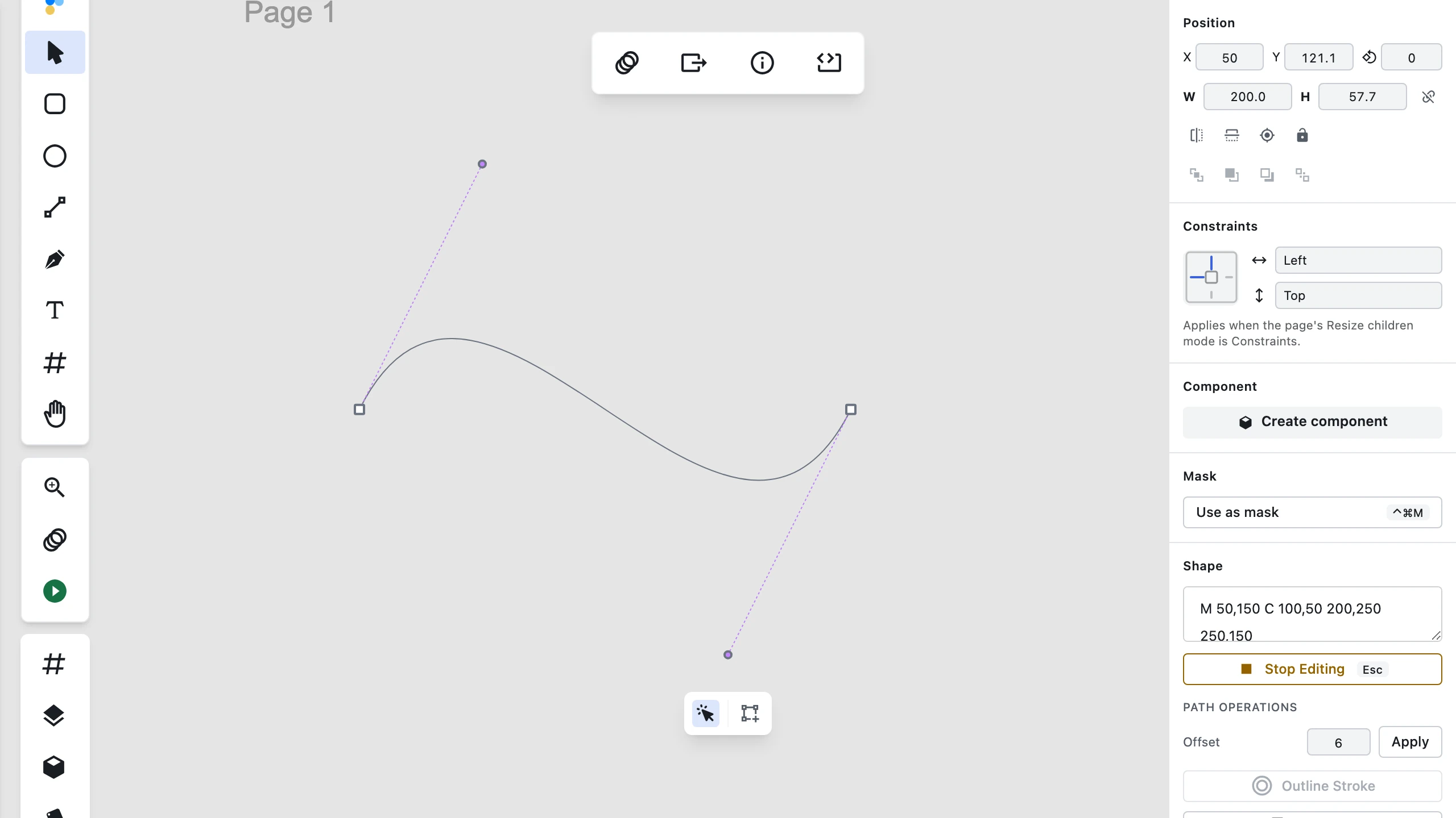
The Pen (P) tool lets you create custom vector paths from scratch directly on the canvas:
- Activating the Pen: Press P or select Pen from the main toolbar.
- Placing corner points: Click anywhere on the canvas to place sharp corner points.
- Drag to curve: Click and press-drag as you place an anchor point to pull out a bézier curve handle. Without modifiers, the drag steers where the path goes next and the segment behind stays straight — hold Shift while dragging instead to curve both sides.
- Shift-drag (smooth points): Hold Shift while dragging an anchor point to curve both sides with mirrored handles.
- Closing the path: Click near the first point to close the loop into a closed shape.
- Finishing an open path: Press Esc or
Ctrl/Cmd + Enterto complete an open path. - Undo: Placing an anchor point, including pulling out its handle curvature, is a single undo step.
For more details on converting point types after placement, see Converting Point Types. To learn more about vector operations, see Vector Operations.
Editing Tools
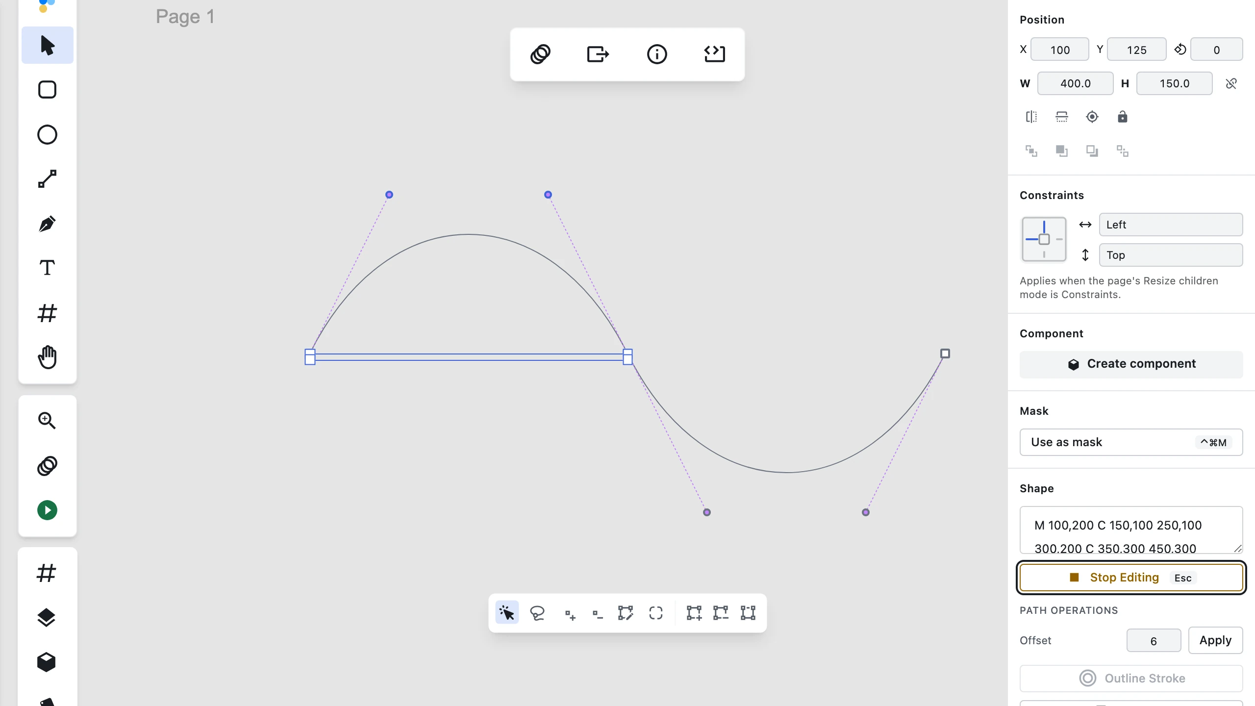
The path editor provides three main tools, accessible from the toolbar at the bottom of the screen:
Select Tool
The Select Tool is your primary tool for modifying existing paths:
- Select points: Click on any anchor point to select it
- Multi-select: Hold Shift while clicking to select multiple points
- Rectangle selection: Drag in empty space to create a selection rectangle
- Additive rectangle selection (
Shift + drag): Hold Shift while dragging a selection rectangle in empty space to add every enclosed anchor point to your existing selection instead of replacing it — the same behaviour as the Lasso tool. Like the Lasso, this selects anchor points only — not segments and not bézier handles. - Move points: Drag selected anchor points to reposition them
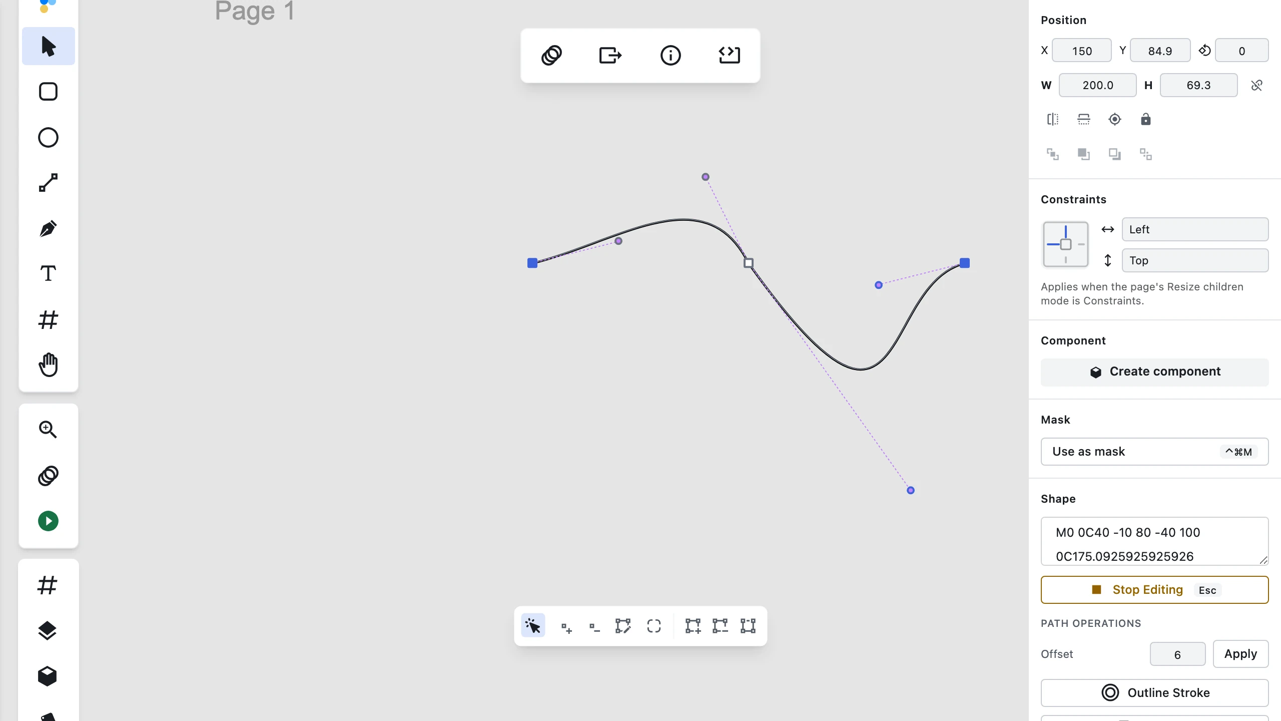
- Adjust curves: Drag control handles (purple dots) to change curve shape
- Convert point types: Double-click on a point to toggle between smooth and corner points
- Parallel handle movement: Hold Shift and click multiple control handles (purple dots) to select them. Dragging any selected handle with Shift held translates all selected handles together in parallel in the same direction, preserving their relative positions.

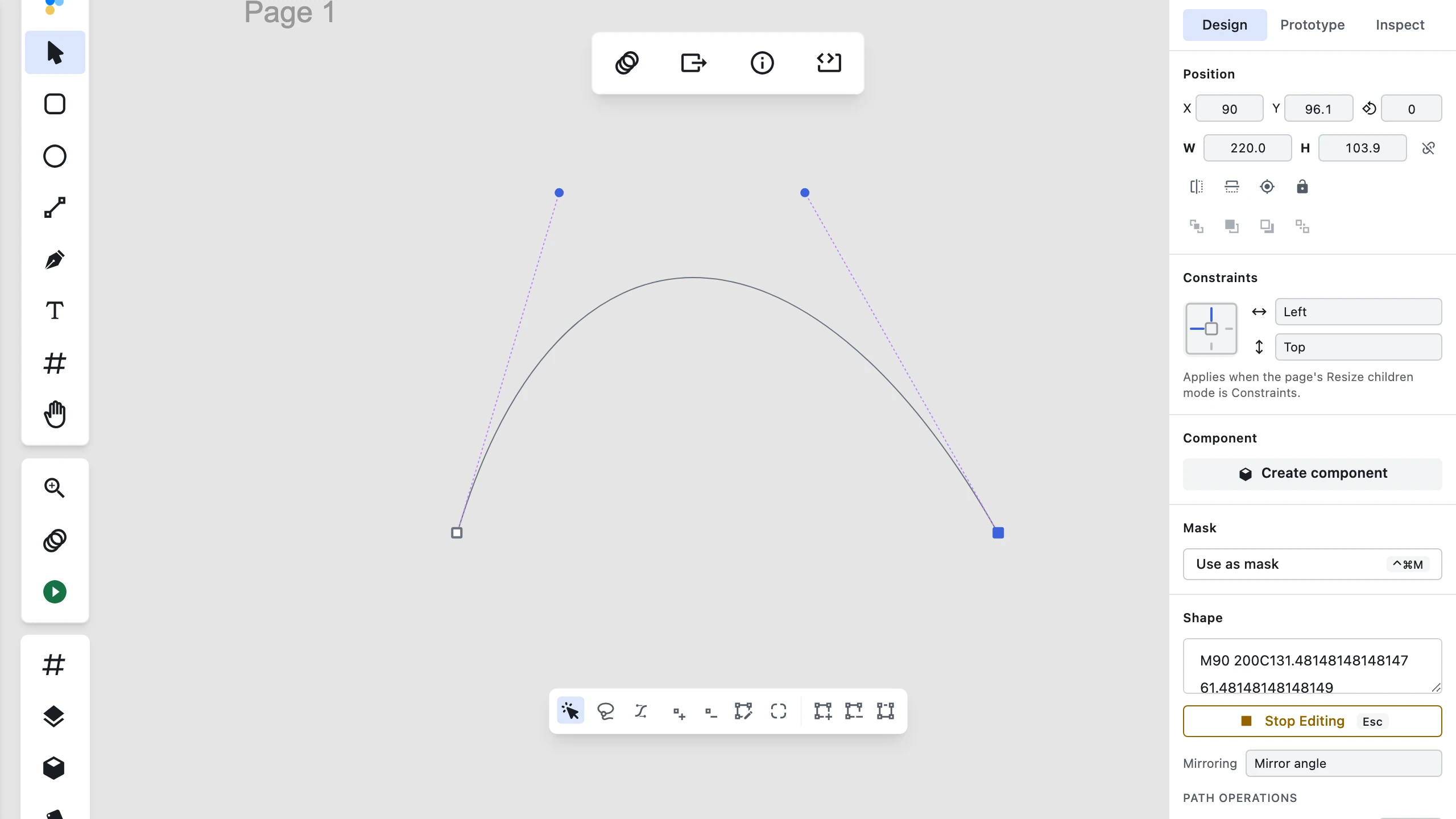

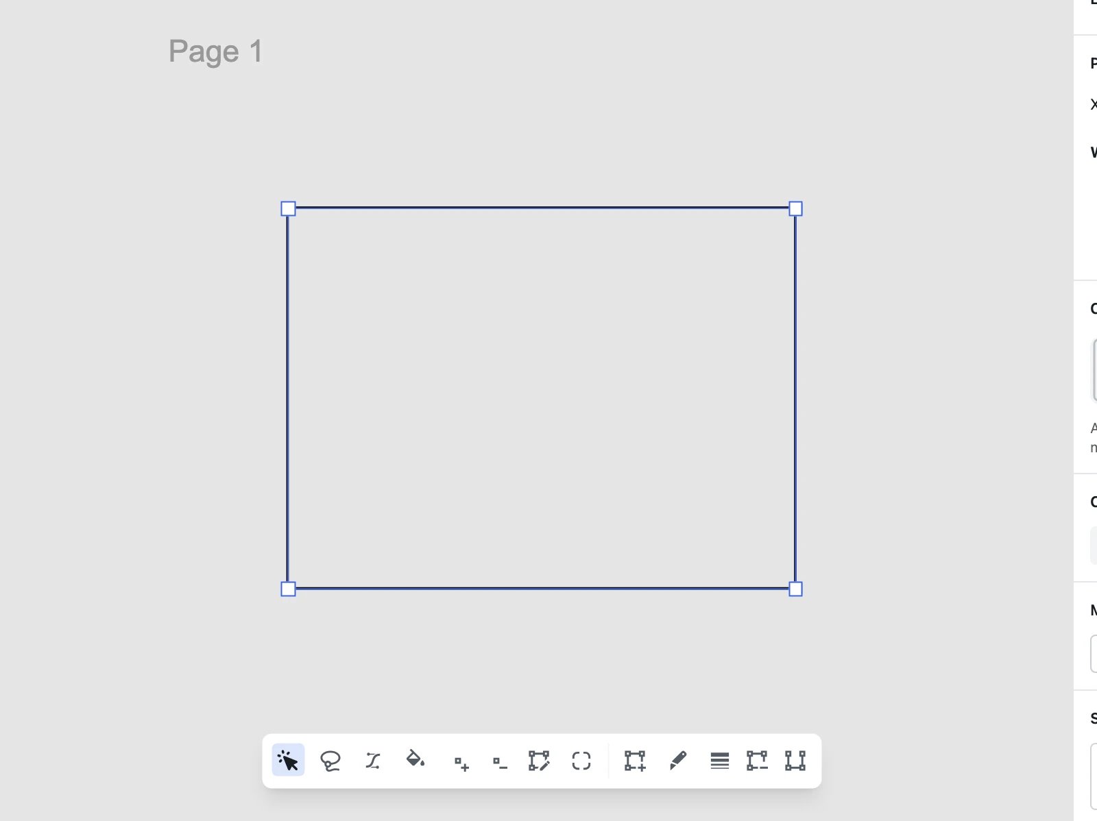
Add Tool
The Add Tool lets you extend your path with new segments:
- Add points: Click anywhere to add a new anchor point
- Preview: As you move your cursor, a preview line shows where the new segment will appear
- Complete segment: Click to place the point and create the segment
- Close path: Click near the starting point to close the path
Insert Tool
The Insert Tool allows you to add detail to existing paths:

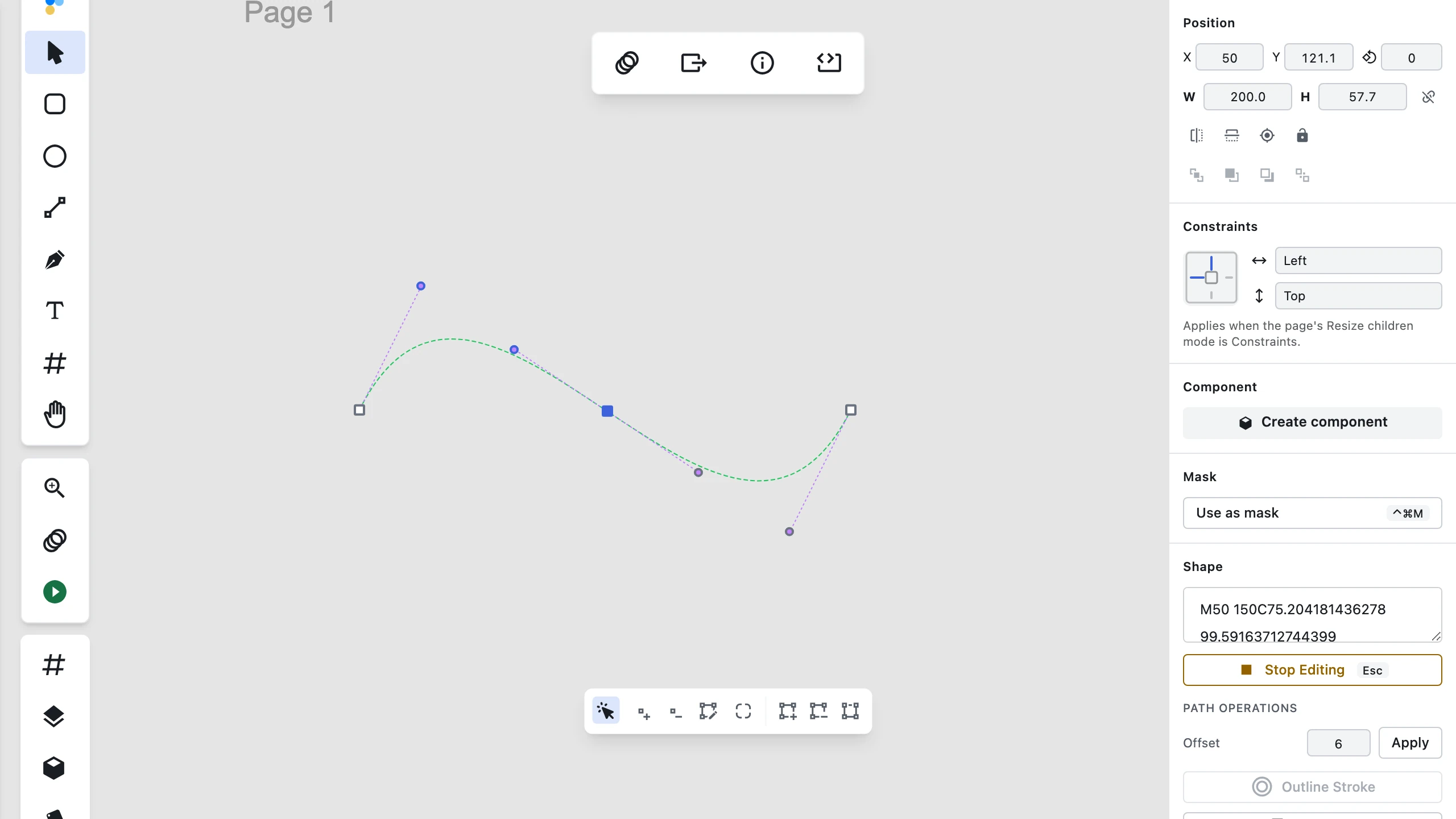
- Insert between points: With an anchor selected, activate Insert Tool to add points between existing segments
- On-path anchor insertion: hover near any straight line or curve segment (Pen
Psub-tool active) to see a preview marker on the path outline. - Shape-neutral placement: click on the path to insert a new anchor point directly at the projected position.
- Automatic curve splitting: straight segments gain a point exactly on the line; curved segments perform a de Casteljau split, adjusting neighboring handles so the rendered shape stays 100% unchanged.
- Subpath safety & undo: the new anchor lands in the hovered subpath only, and the whole insertion reverts in a single
Cmd/Ctrl+Z. - Drag-to-curve placement: Press and drag while placing a point (or when extending an existing open path) to pull out a curve handle on the fly; hold Shift while dragging to curve both sides with mirrored handles
- Maintain curves: When inserting between curved segments, the tool preserves the original curve shape
- Close path: Click near the first point of an open path to close it with a smooth curve
Bend Tool

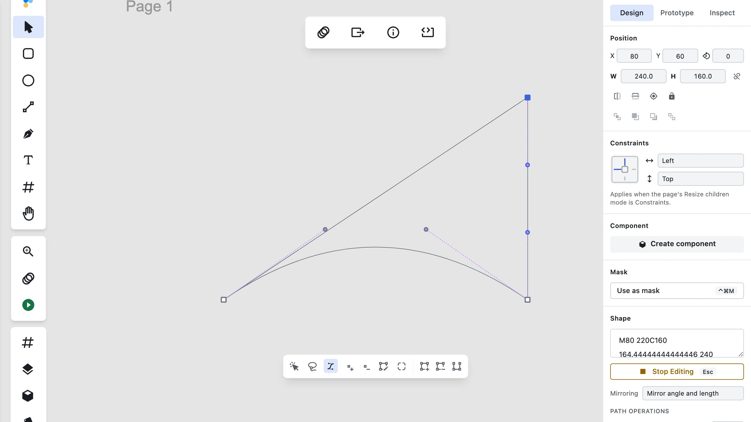
The Bend Tool provides a direct-manipulation gesture for bending vector path segments into curves and adding bézier handles:
- Activate Bend Tool: Select Bend from the vector editing secondary toolbar at the bottom of the canvas (or click its icon after Lasso).
- Bend Path Segments: Hover over any straight or curved path segment to reveal a green highlight and grab cursor. Click and drag anywhere on the segment away from anchor points to pull it into a curve following your pointer live. Bounding anchors automatically gain or adjust handles facing that segment without moving adjacent segments.
- Convert Corner Anchors: Click directly on a sharp corner anchor (a point with no handles) to convert it into a curved point with new bézier handles aligned along the local tangent.
- Cancel Gesture (
Esc): Press Esc mid-drag to cancel an in-flight bend gesture and revert path geometry. - Single Undo Step: Bending a segment or converting an anchor with the Bend tool is recorded as a single undo step (
Cmd/Ctrl + Z).
Paint Tool (Shift + B)

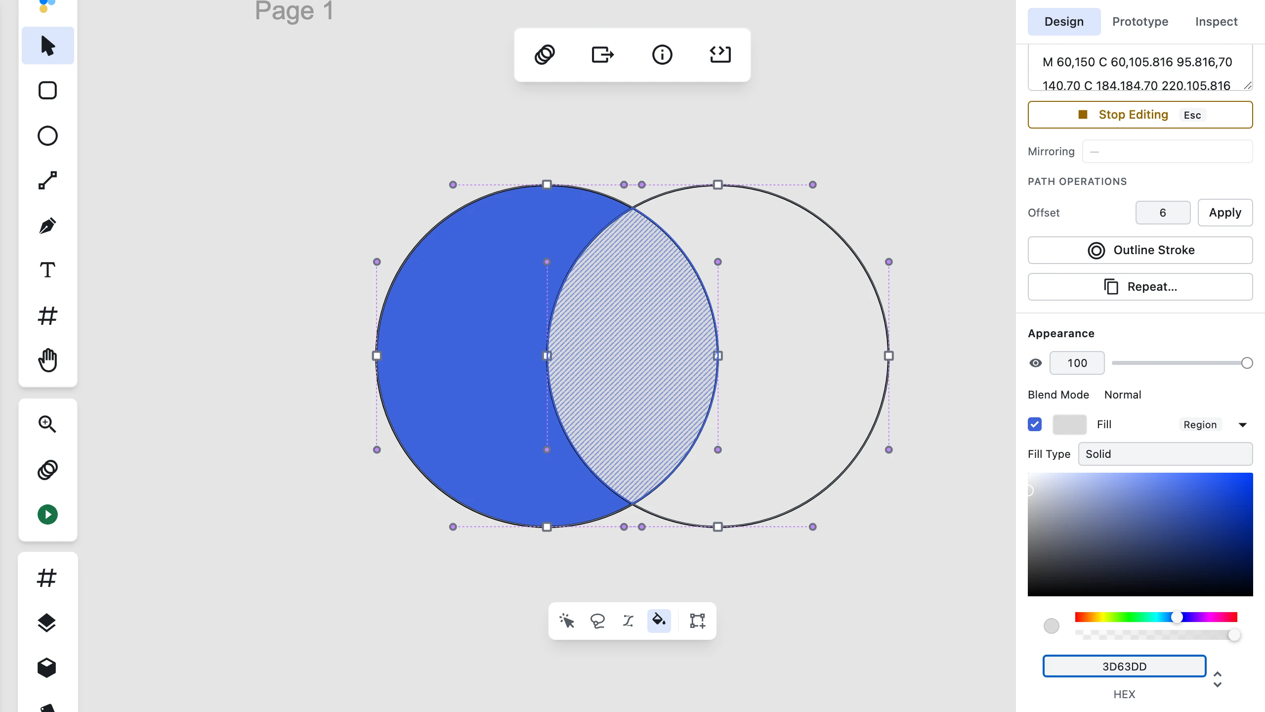
The Paint Tool fills individual closed regions of a path — including the regions formed where two or more subpaths overlap — instead of coloring the whole layer at once:
- Activate Paint Tool: Press Shift + B, or select Paint from the vector editing secondary toolbar (right after Bend), while vector edit mode is active. Outside vector edit mode,
Shift + Bdoes nothing. - Hover a Region: Moving the pointer over the artwork highlights the closed region directly under it with a diagonal stripe hatch, and the cursor shows a droplet with a plus over an unfilled region or a droplet with a minus over a filled one. Hovering the partially-enclosed area of an unclosed (open) path shows no hatch and an unfillable droplet cursor — clicking there does nothing.
- Click to Fill or Unfill: Clicking an unfilled region fills it with Figpea's default fill color; clicking an already-filled region removes its fill. Only the clicked region changes — every other region, including the non-overlapping parts of an overlap region, is left exactly as it was. Each click is a single undo step (
Cmd/Ctrl + Z). - Edit a Region's Color: Clicking a region selects it, and the right sidebar's Fill section scopes to it — a Region chip appears beside the Fill label, and changing the color there (solid colors only) updates only that region.
- Overlapping Subpaths: Where two subpaths overlap, the overlap is its own independently fillable region — filling or clearing it never touches the two subpaths' non-overlapping areas.
- Persistence & Export: Per-region fills are saved with the project and reproduced faithfully in SVG export, matching the on-canvas render.
Lasso Tool


The Lasso Tool lets you select anchor points with a freeform drag gesture in vector edit mode:
- Activate Lasso Tool: Press Q or select Lasso from the path editing secondary toolbar at the bottom of the canvas.
- Freeform Selection: Click and drag to draw a freeform loop around the anchor points you want to select. On pointer release, the selection loop automatically closes by connecting the release point back to the start point.
- Screen-Space Hit Testing: Anchor enclosure is evaluated in screen space against rendered anchor dots, keeping selection accurate across rotated, scaled, or sheared vector layers.
- Additive Selection (
Shift + Drag): Hold Shift while drawing with the Lasso tool to add newly enclosed anchor points to your existing selection without clearing prior selections. - Cancel Selection (
Esc): Press Esc while drawing a lasso loop to abandon the drag gesture without changing the current selection, returning to the Select tool while keeping vector edit mode active. - Consuming Operations: Selected anchor points can be translated together, deleted (
Delete), converted (Convert To), or rounded (Round Corners) in a single step. Note that Lasso currently selects anchor points only (not path segments/edges or bézier handles).
Cut Tool
The Cut Tool lets you divide vector objects exactly where you want:
- Toolbar & Shortcut: Activate the Cut tool via the secondary toolbar or by pressing C while vector edit mode is active.
- Click-to-split: Click an anchor point to open a closed path, or click a position along an open-path segment to split it into two subpaths, preserving the rendered outline.
- Drag-to-divide: Drag a straight cut line across a closed shape to divide it into two sibling layers, both inheriting the source layer's fill, stroke, opacity, blend mode, and effects, with names derived from the original layer.
- Live preview & gestures: The hover split indicator and drag preview line show exact intersection points; Esc cancels an active drag without modifying geometry; Cmd/Ctrl+Z undoes the entire cut gesture in a single history step.
- Scope boundary: Cut divides along a straight line only and confines a divide to layers already in the current vector edit session.
Variable Width Tool

The Variable Width tool allows you to change a stroke's thickness at any point along a vector path in vector edit mode:
- How to Activate: Select a path layer with a solid stroke, enter path editing mode (
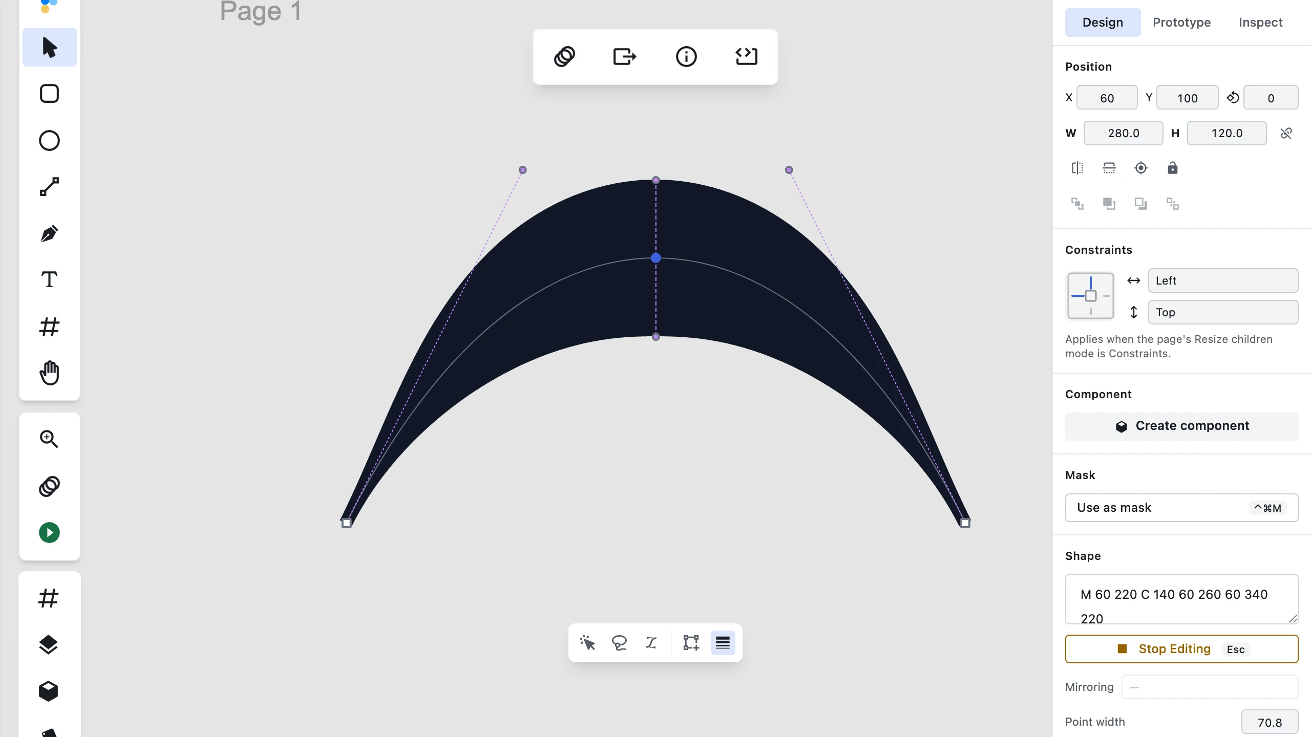
Enter), and activate Variable width from the secondary toolbar at the bottom of the canvas. - Adding Width Points: Hover the pointer over the stroke to preview a width handle at the projected position; click to place a new width point.
- Adjusting Stroke Thickness: Drag the width handles outward or inward to expand or contract the stroke thickness at that position. The rendered stroke smoothly tapers between neighboring width points or path ends. You can also select a width point and type an exact numeric width in the Inspector's width field.
- Repositioning & Multi-Selection: Drag any width point along the path outline to move it to a new location while preserving its thickness value.
Shift + clickto select multiple width points; pressDeleteto remove selected width points and restore uniform stroke width in those regions. - Snapping & Overrides: Width points automatically snap to vector anchor points, midpoints between vector anchors, and midpoints between existing width points. Hold
Ctrlduring the drag gesture to temporarily bypass snapping. - Declining Conditions & Split Vector:
- Dashed Strokes: Variable width declines on dashed strokes with an explicit message ("Variable width is not supported on dashed strokes").
- Branching Paths / Multiple Subpaths: Variable width declines on paths with multiple subpaths ("Variable width requires a single subpath"). Right-click the multi-subpath layer on canvas and select Split vector to separate it into individual single-subpath layers using Figpea's
splitPath()engine, after which Variable width accepts each resulting layer.
- Rendering, Export & Undo: Variable-width strokes render on canvas as filled outlines that follow the width profile, and SVG export reproduces the same filled outline without clipping — the exported document's framing encompasses the full variable-width extent, even on widening profiles, matching the on-canvas render. Every width-point modification (add, handle drag, numeric edit, reposition, delete, split) reverts in a single Cmd/Ctrl+Z step.
Scripted counterpart: agents read and write this same width profile as figpea.layer.getVariableWidth / figpea.layer.setVariableWidth — see /docs/agent-api.
For more details, see Vector Operations and Exporting.
Transforming Multiple Anchor Points (Bounding Box)
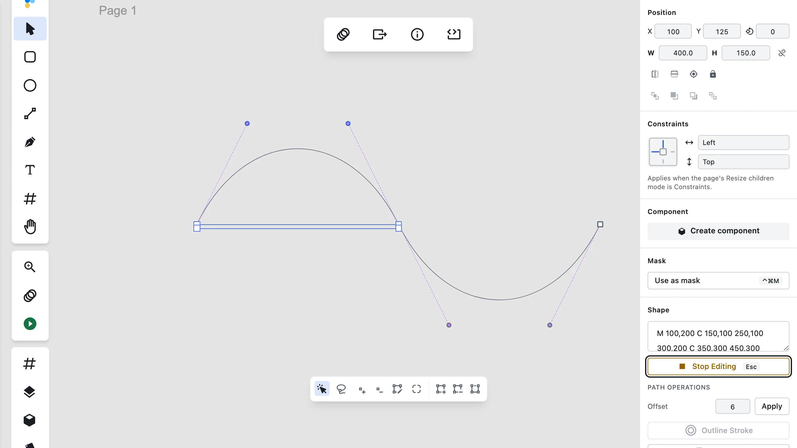
When you select two or more anchor points in vector edit mode, an interactive bounding box appears around them, allowing you to adjust their size, position, and rotation as a group without affecting the rest of the vector network:
- Scale anchors: Drag any corner or edge handle to scale selected anchor points and their attached bézier handles about the opposite handle. Unselected anchors remain stationary.
- Proportional scale (
Shift): Hold Shift while dragging a handle to preserve the aspect ratio of the selected anchor group. - Scale from center (
Alt/Option): Hold Alt (Windows) / Option (macOS) while dragging to scale the points relative to the center of the selection bounding box. - Rotate anchors: Move the pointer slightly outside a corner handle until the rotation cursor appears, then drag to rotate selected anchors about the box center.
- Snap rotation (
Shift): Hold Shift while rotating to snap the rotation angle to 15° increments. - Reposition mid-gesture (
Space): Press and hold Space during an active scale or rotate gesture to translate the selection across the canvas. Releasing Space resumes the scale or rotate operation from the new position. - Undo: Each completed transform gesture reverts in a single Cmd/Ctrl + Z step.
Multi-Layer Vector Editing
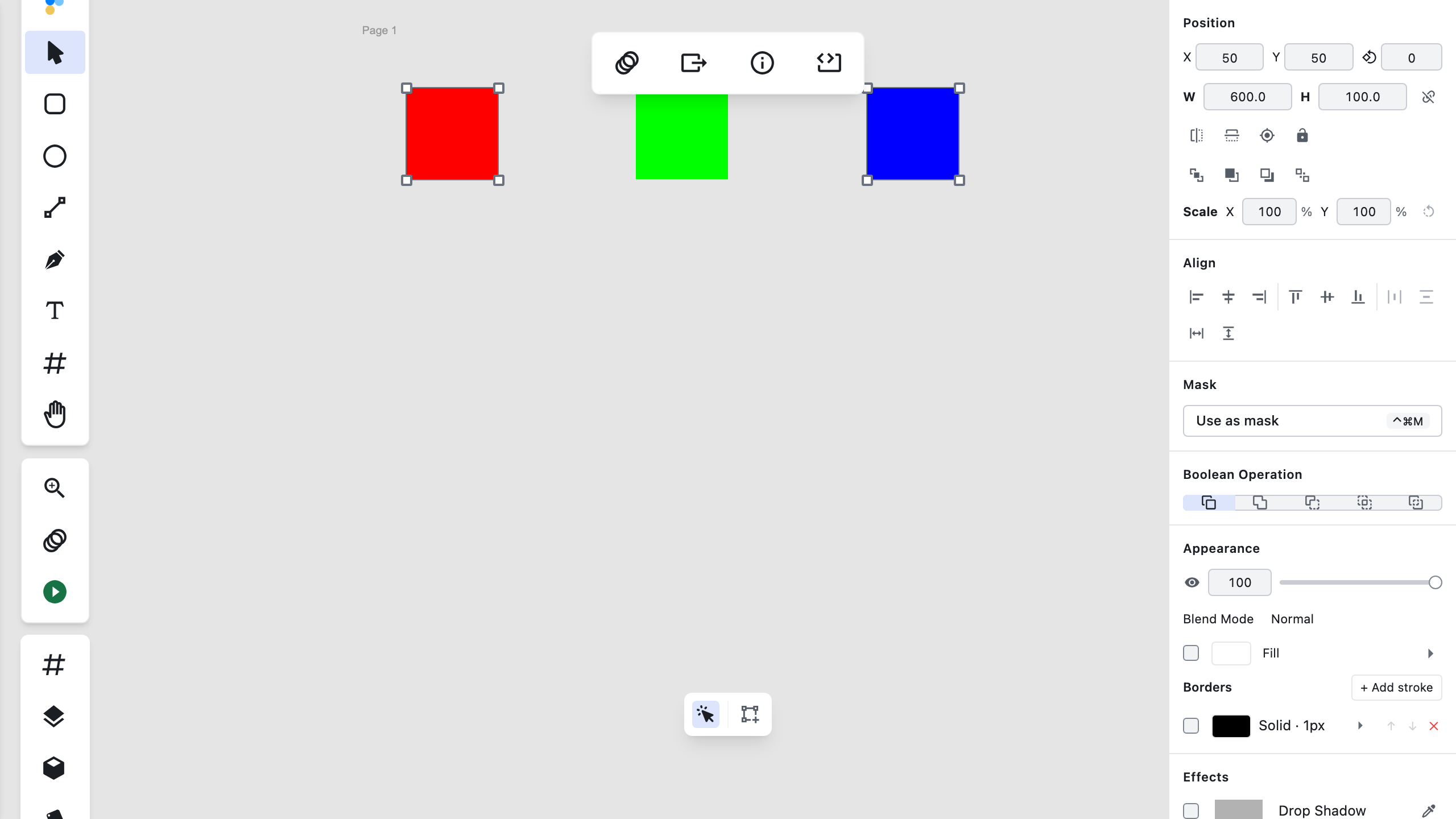
You can edit multiple vector paths in a single session without losing your tool state or anchor selections:
- Multi-selection entry: Select two or more path/shape layers on canvas and press Enter.
- Adding layers (
Shift + click): Hold Shift and click on the body of another path layer on canvas to add it to your active vector edit session. - Switching layers (
Cmd/Ctrl + click): Hold Cmd (macOS) / Ctrl (Windows) and click on the body of another path layer to switch the session directly to that layer. - Anchor dot disambiguation: Clicking directly on an anchor or control point with Cmd/Ctrl held still adds/modifies anchor selections and never triggers a layer switch.
- Per-layer undo: Edits to each layer in the session are independently isolated in history. Pressing
Cmd/Ctrl + Zundoes your last vector modification in reverse order. - Escape ladder: Pressing Esc once clears anchor selections while keeping the multi-layer session active; pressing Esc a second time exits vector edit mode entirely.
Editing a mask's path
A vector mask is a shape with a path, so it edits like one. Select the mask layer — the row carrying the mask indicator (see Masks for how to spot it) — and press Enter or click Edit Path, exactly as for any path. Anchors and bézier handles appear on the mask's outline, and the Select, Add, Insert, Bend, and Cut tools all work the same way they do on any other path.
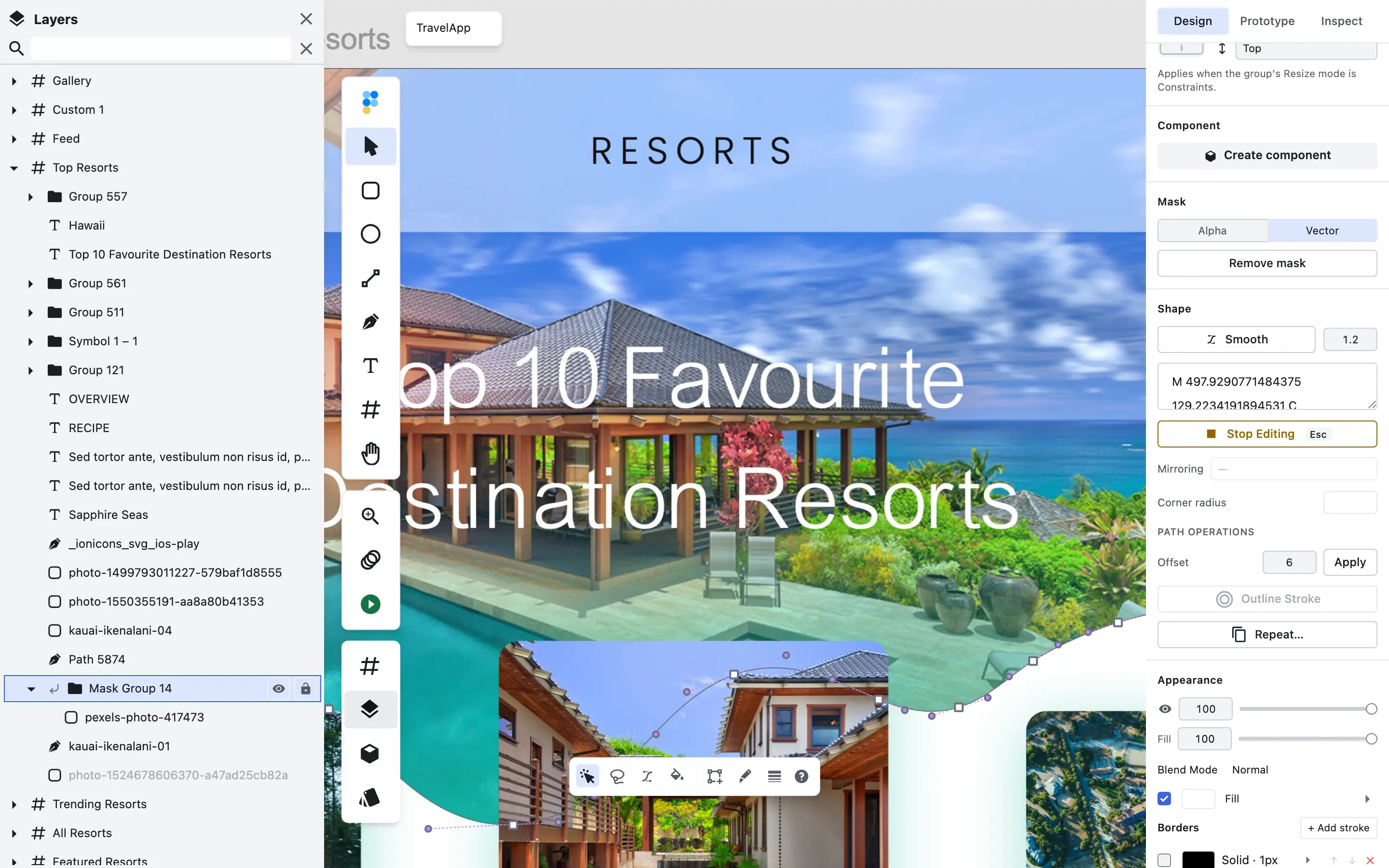
This only applies to masks with path geometry — a shape layer used as a mask. An alpha mask on an image, text, or folder layer has no path to edit, so pressing Enter there does nothing.
Drag an anchor or handle and the masked render follows the edit live: the clipped content reshapes as you pull.

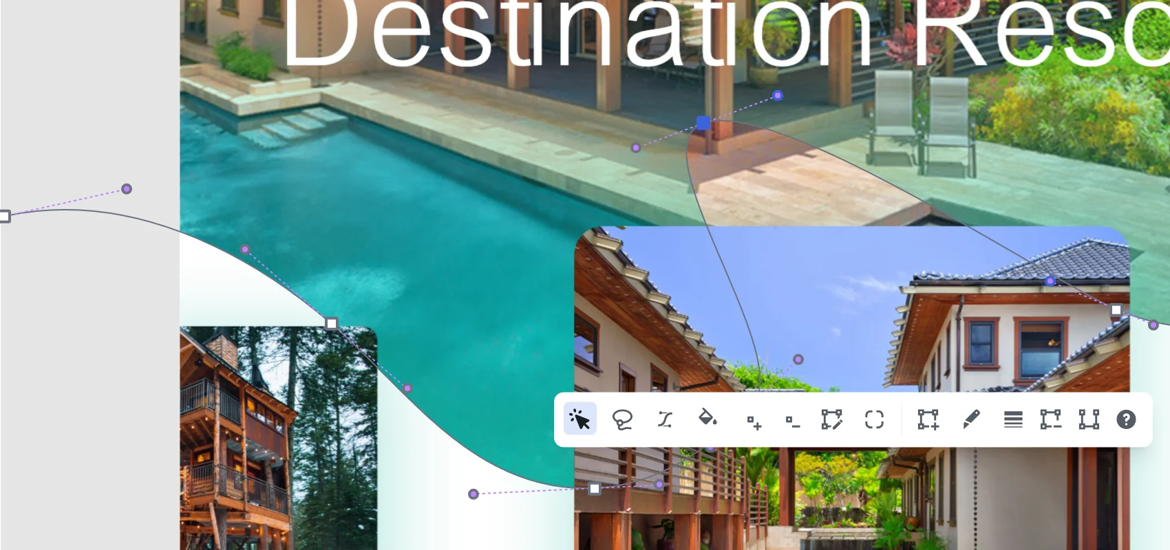
Like any path edit, the change undoes with Cmd/Ctrl + Z. For handle work, see Converting Point Types. To create, retype, or remove a mask, see Masks — this section is about reshaping the outline your file brought with it.
Path Operations
Working with Points
- Delete points: Select one or more points and click the Delete button
- Insert after: Select a point and click Insert After to add a new point after it
- Remove segment: Select a point and click Remove Segment to delete the entire segment
Converting Point Types
You can convert selected points to different types using the Convert To menu:
- Line segments: Creates straight lines with corner points
- Curve segments: Creates smooth Bézier curves
- Horizontal/vertical lines: Creates perfectly horizontal or vertical line segments
Opening and Closing Paths
- Close path: Connect the last point to the first point to create a closed shape
- Open path: Break a closed path to create an open path
Round Corners
Round Corners replaces each selected corner with a clean tangent arc of the radius you type — softening a logo, rounding a polygon or star, or taking the hard edges off an imported path.
To apply Round Corners, first open Edit Path mode by selecting a path layer and clicking the Edit Path button. Select one or more corner points (Shift-click to add to the selection, or drag a selection rectangle around multiple points), then click the Round Corners button, type a radius value, and click Apply. The operation applies only to the corners you selected, and all selected corners are rounded with a single radius value—per-corner radii are not supported.
This is a destructive operation: one undo reverses it completely. If you apply Round Corners again to a corner that is already rounded, nothing happens—those points now sit on a curved segment, and curved corners are skipped.
Only corners between straight segments can be rounded. A corner with a curved segment on either side is skipped, and the rest of your selection is still rounded; the count of roundable corners is shown before you apply so you know what to expect. A radius too large for a corner is automatically reduced to the largest radius that fits, rather than being silently ignored.
This is not the rectangle's corner radius property in the Rect section of the Inspector, which stays live and re-editable and can carry four different values per corner. Round Corners rewrites the path itself: a rectangle's corner radius exports as CSS border-radius, while a rounded path exports as path geometry.
For more about working with anchor points, see Working with Points and Converting Point Types. To learn more about vector operations, see Vector Operations. For information about exporting your rounded paths, see Exporting.
Scripted counterpart: agents call this same corner-rounding operation as figpea.layer.roundCorners — see /docs/agent-api.
Parametric Corner radius (Right Sidebar)
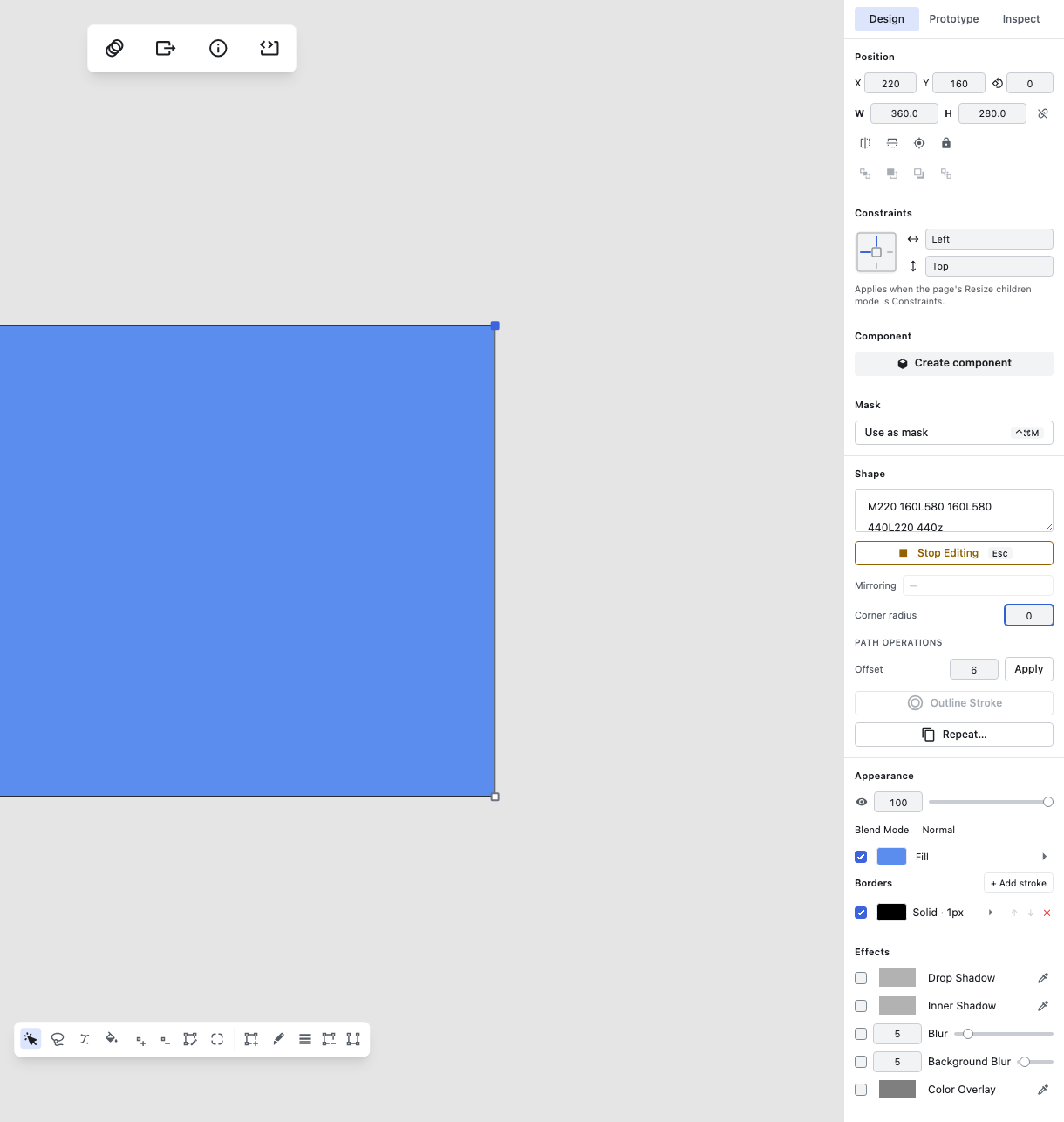

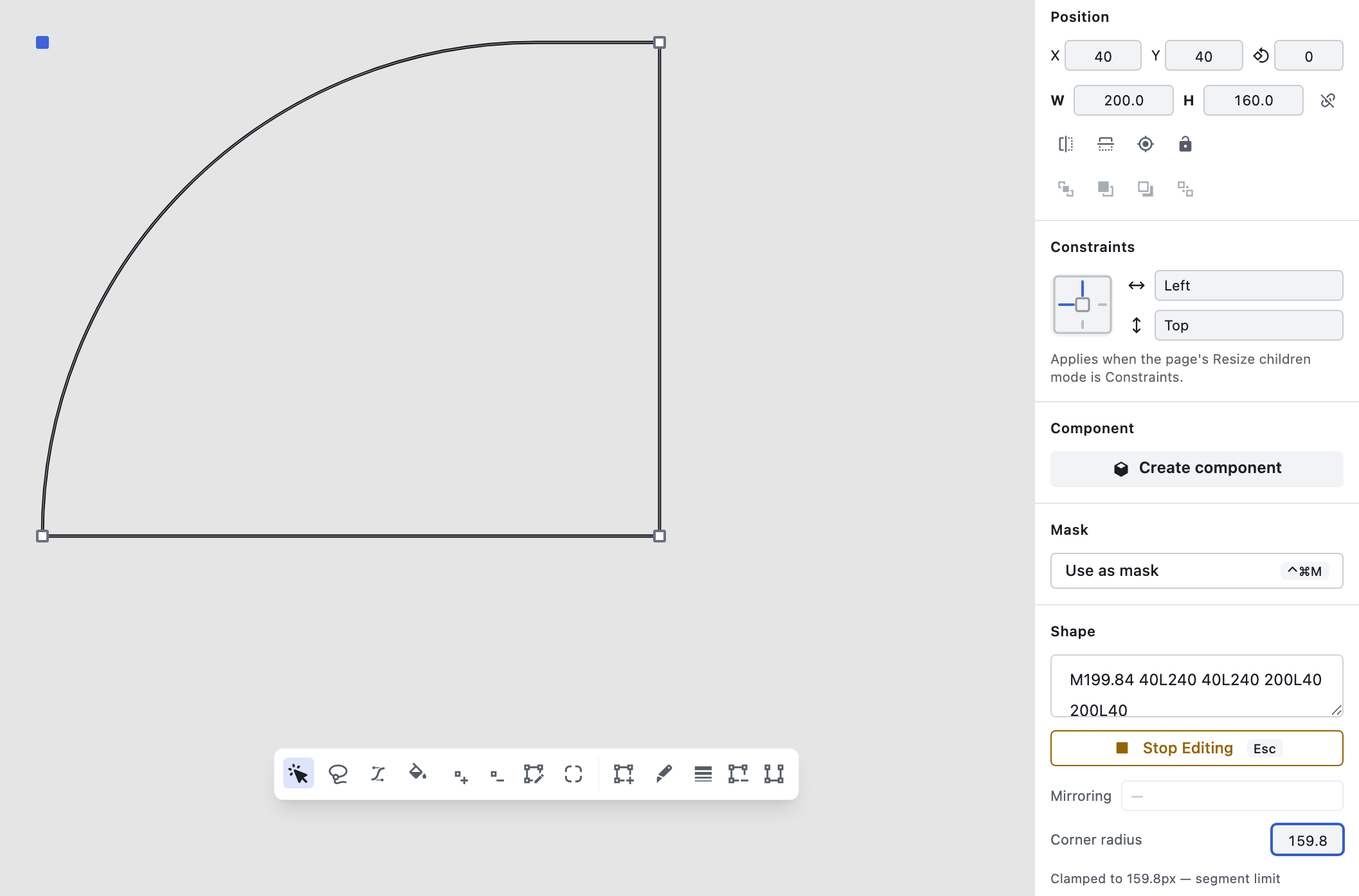
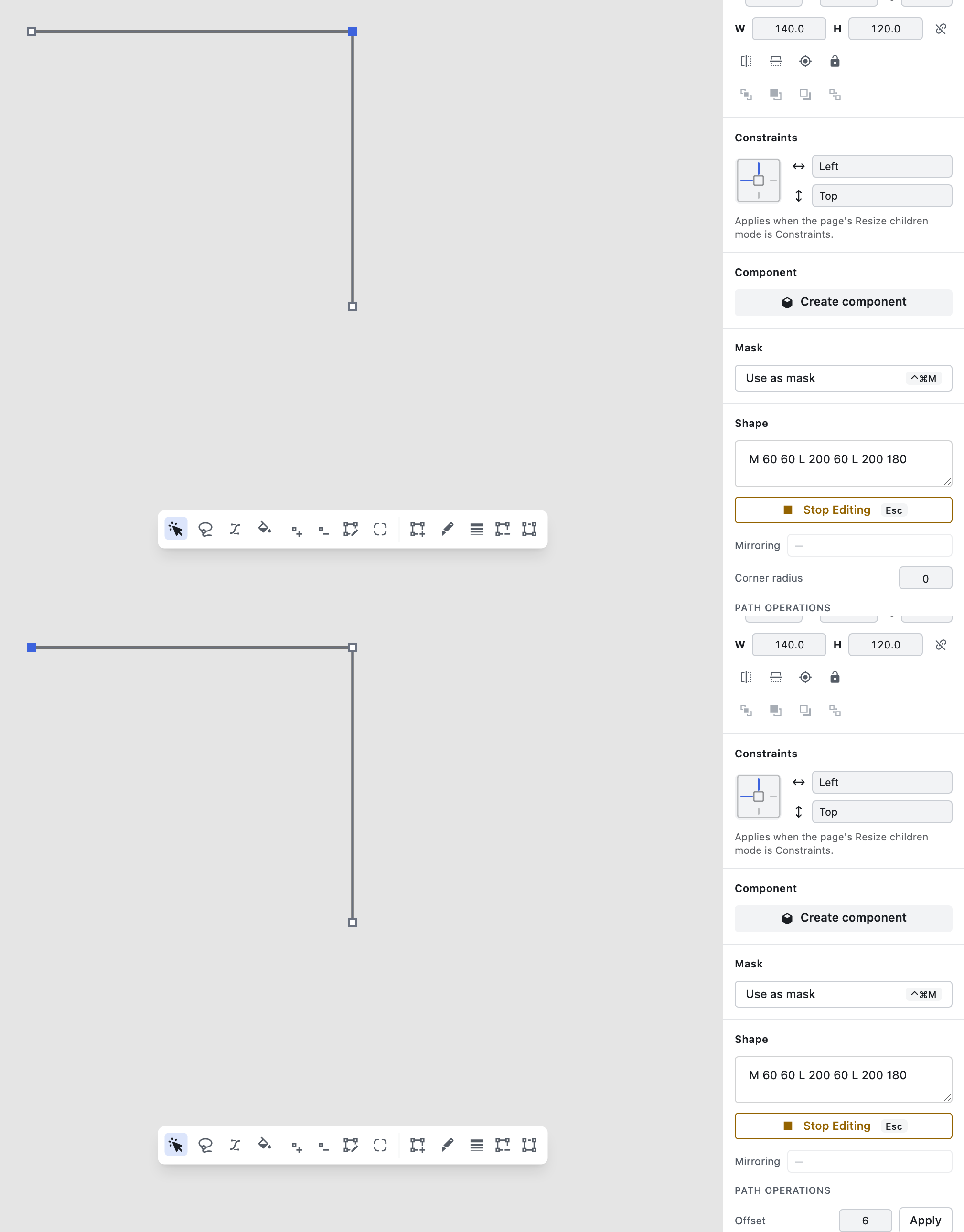
Beyond the toolbar operation above, Figpea also offers a live, re-editable Corner radius property in the right sidebar for individual anchor points — a separate, parametric way to round the same kind of corner. When one or more straight corner anchor points are selected in vector edit mode (Enter), the right sidebar shows a Corner radius field for the current selection:
- Re-editable & Non-Destructive: change the value at any time — re-tuning always recomputes from the corner's original sharp geometry, so edits never compound.
- Zero-Reset: setting the value back to
0restores the corner to its original sharp geometry, byte-identical to before any radius was ever applied. - Mixed States & Multi-Point: selecting multiple corners with different radii shows a "Mixed" placeholder; typing a value applies it to every selected corner that can be rounded.
- Clamping & Eligibility: a radius larger than a corner's adjacent segments allow is automatically clamped, and the applied value is shown back so the clamp is never silent. A curved corner shows the field disabled with a reason; selecting only open-path endpoints hides the field entirely.
- Persistence & Undo: radii are saved with the project (
.fp), exported as SVG arcs, and one undo step reverts a radius change together with the corner geometry it produced.
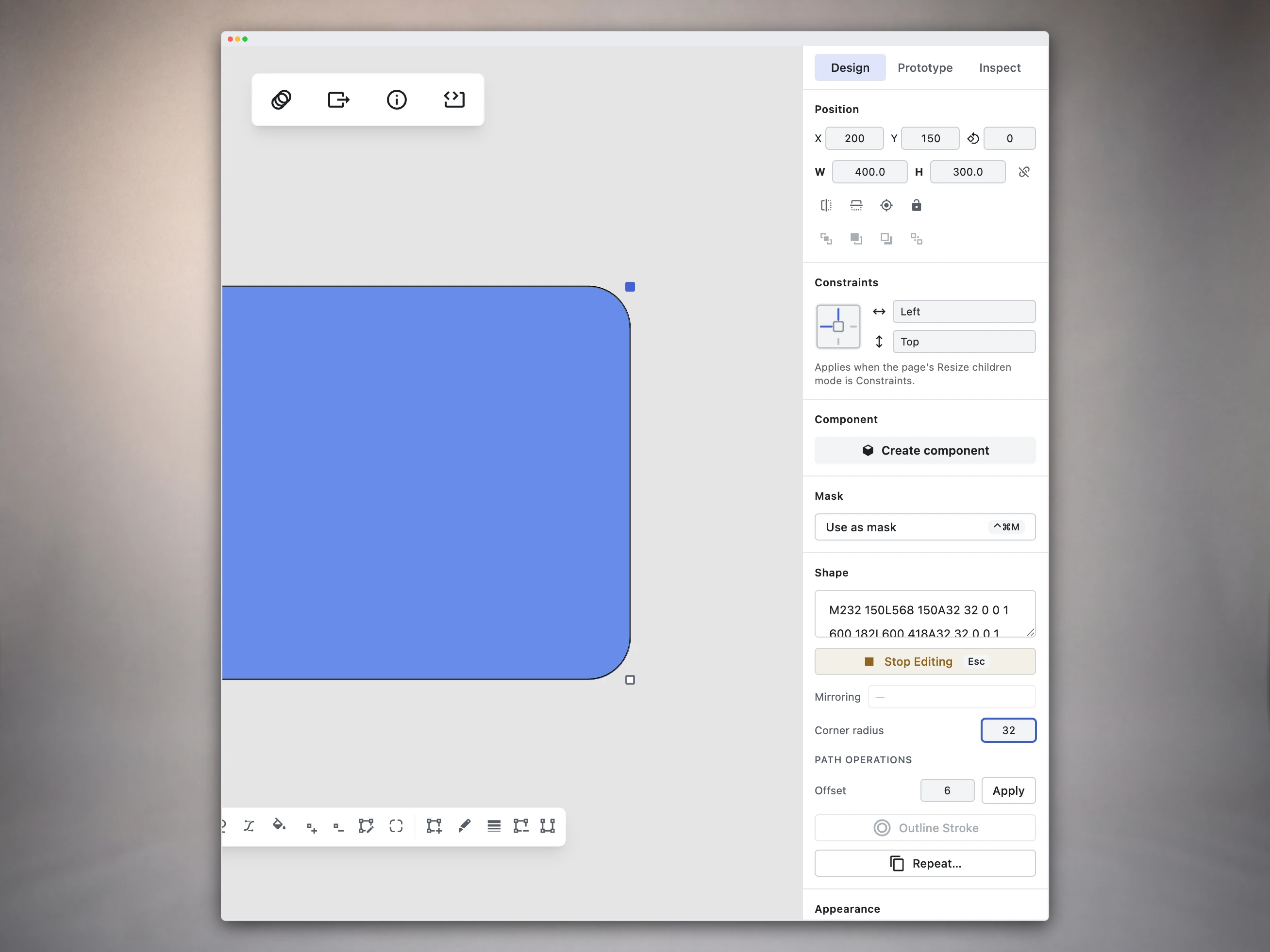

Destructive Round Corners (Toolbar)
The Round Corners toolbar operation described above and the Corner radius sidebar property above are two different tools for the same kind of corner, and it's worth being clear about which is which: the toolbar operation bakes an arc into the path and deletes the original anchor — the only way back is undo. The sidebar property is a value on the anchor itself, so you can select that corner again later and change or remove its radius without undoing anything.
Point Mirroring Options
Anchor points with bézier handles carry a stored Mirroring property that controls how opposite handles interact during a drag:
- No mirroring: Handles move completely independently. Dragging one handle adjusts its angle and length without changing the opposite handle's position.
- Mirror angle: Handles maintain a collinear 180° line through the anchor point, but their lengths can be adjusted independently (asymmetric handles).
- Mirror angle and length: Handles maintain both an identical angle and equal length across the anchor point (symmetrical handles).
Using Point Mirroring in the Inspector:
- Select one or more anchor points in vector edit mode.
- In the Vector Inspector panel, locate the Mirroring dropdown.
- Choose No mirroring, Mirror angle, or Mirror angle and length.
- Plain handle drags (with no modifier keys held) strictly obey the point's stored mirroring mode.
- Point mirroring modes persist across project saves (
.fp) and reopens. Imported PSD, XD,.fig, and SVG vector paths automatically infer mirroring modes per point based on initial handle geometry. - When selecting multiple anchors with differing modes, the inspector displays a mixed state. Selecting a mode applies it to all selected points.
Keyboard Shortcuts and Modifiers
Use these keyboard modifiers for precise control:
| Key | Function |
|---|---|
Shift + drag handle | Move multi-selected bézier handles together in parallel direction (parallel handle translation) |
Bend Tool | Select Bend tool from secondary toolbar to drag path segments into curves or convert corner anchors to bézier handles |
Shift + B | Activate Paint tool in vector edit mode to fill or unfill individual closed path regions. |
Enter | Enter vector edit mode on selected path/shape layers (converting non-paths to paths first) |
Q | Activate the Lasso tool for freeform anchor point selection in vector edit mode |
C | Activate the Cut tool in vector edit mode |
Shift + click on layer body | Add a path layer to the active multi-layer vector edit session |
Cmd/Ctrl + click on layer body | Switch active layer in vector edit session without exiting |
Shift | When moving control points: Maintain symmetrical handles (mirrored — same angle & length) |
Alt / Option | When dragging a control handle: Move it independently, breaking symmetry (the opposite handle stays where it is) |
Shift (with Lasso tool) | Hold Shift while dragging with the Lasso tool to add points to the current anchor selection |
Shift + drag (selection rectangle) | Add enclosed anchor points to the current anchor selection (same as Shift with the Lasso tool) |
Shift (while scaling handles) | Preserve aspect ratio (proportional scale) of selected anchor points |
Alt / Option (while scaling handles) | Scale selected anchor points from the center of the selection bounding box |
Shift (while rotating corner) | Snap rotation angle to 15° increments |
Space (during scale/rotate gesture) | Hold Space mid-gesture to translate the selection, then release Space to resume transform |
Ctrl / Cmd | When dragging a control handle: Constrain the handle movement to 45° increments |
Esc | With the Add, Insert, Lasso, or Cut tool active: cancel it and return to the Select tool. With the Select tool: clear the selected anchor points (first press), or leave path editing when nothing is selected (second press). |
Ctrl/Cmd + Enter | Leave path editing straight away, whichever tool is active. |
Double-click | Toggle between smooth and corner points |
Leaving path editing is not an undo: whatever you changed stays changed. Use Ctrl/Cmd + Z to undo an edit.
Snapping Features
The path editor includes intelligent snapping to help you create precise paths:
- Point snapping: Automatically snap to existing anchor points
- Alignment snapping: Snap to horizontal or vertical alignments with other points
- Visual guides: Green dotted lines appear when snapping is active
While using the Add or Insert tool, hold the Alt key to temporarily disable snapping. Alt does not bypass snapping during a handle drag.
Best Practices
Creating Clean Paths
- Start simple: Begin with basic shapes and add detail gradually
- Use minimal points: Fewer points create smoother, more efficient paths
- Leverage curves: Use curves instead of many straight segments for smooth shapes
- Maintain symmetry: Use Shift when adjusting control handles for symmetrical curves
Editing Efficiently
- Choose the right tool: Use Select for adjustments, Add for new segments, Insert for adding detail
- Use keyboard modifiers: Shift, Alt, and Ctrl/Cmd provide precise control
- Utilize snapping: Enable snapping for precise alignment with other elements
- Convert point types: Use the Convert To feature to change how segments connect
Troubleshooting
Common Issues
- Points not selecting: Make sure you're using the Select tool and clicking directly on the point
- Unexpected curve behavior: Check control point positions and consider converting between point types
- Snapping not working: Make sure you're not holding Alt while using the Add or Insert tool — Alt temporarily disables snapping only for those tools, not during a handle drag
- Path segments disappearing: This can happen when deleting critical points; use Undo if needed
Advanced Techniques
Creating Complex Shapes
For complex shapes:
- Break the shape into multiple path segments
- Use a combination of curves and straight lines
- Leverage the Convert To feature to change segment types as needed
Precision Editing
For precise control:
- Zoom in for detailed work on small areas
- Use the Insert tool to add detail to specific areas
- Leverage snapping to align with existing elements
- Use keyboard modifiers for fine-tuned adjustments